


— Blogs —
—Products—
 Consumer hotline +8618073152920
 WhatsApp:+8615367865107
Address:Room 102, District D, Houhu Industrial Park, Yuelu District, Changsha City, Hunan Province, China
Technical Support
Time:2024-07-14 22:58:05 Popularity:3233
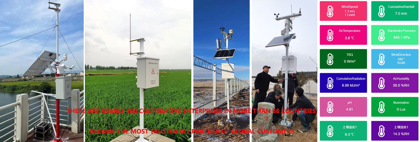
There are a number of steps and methods that need to be followed in order to connect multiple RS485 sensors to the RS485 interface of an industrial router(Gateway/Data Collector/Data Logger) for data acquisition. The following is a detailed guide:
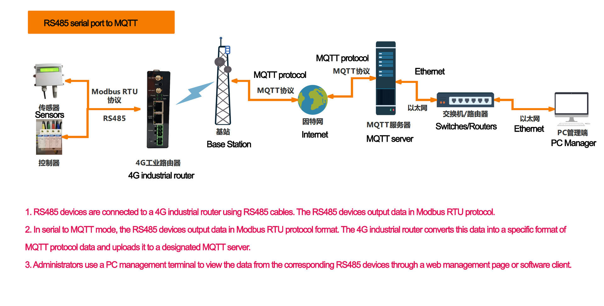
1. RS485 devices are connected to a 4G industrial router using RS485 cables. The RS485 devices output data in Modbus RTU protocol.
2. In serial to MQTT mode, the RS485 devices output data in Modbus RTU protocol format. The 4G industrial router converts this data into a specific format of MQTT protocol data and uploads it to a designated MQTT server.
3. Administrators use a PC management terminal to view the data from the corresponding RS485 devices through a web management page or software client.
I. Preparation
1. Confirm the hardware interface
1. 1 Check the RS485 interface of the industrial router: Confirm whether the industrial router has an RS485 interface, usually it will have a standard RS485 serial port or through an RS485 converter module to achieve the interface function.
1.2. Confirm RS485 sensor interface: Make sure each RS485 sensor has an RS485 interface for data communication.
2. Confirm device compatibility:
Ensure that all RS485 sensors and industrial routers have compatible RS485 interfaces, including electrical characteristics and communication protocols (e.g. baud rate, data bits, stop bits, parity, etc.).
Check the product manuals of the sensors and industrial routers or contact the suppliers for detailed information.
3. Prepare the necessary tools and materials:
-Wiring terminals or connectors (if necessary)
-Tools such as screwdrivers, wire strippers, etc.
- RS485 sensor or module
- Industrial router (Gateway/Data Collector/Data Logger) with RS485 interface
- Patch cords or twisted-pair cables (according to the interface definition, compliant with the RS485 standard, usually shielded twisted-pair cables)
- Terminating resistor (optional)
- Power supply
- Possible protection devices, e.g. surge protectors
II. Connection steps
1. Connect the RS485 sensors:
Use a twisted pair cable to connect the RS485 interface of each RS485 sensor. Make sure the cable is wired correctly, usually A (or +) and B (or -) are connected in correspondence.
If the sensors are far away, consider using a repeater or signal amplifier to boost the signal.
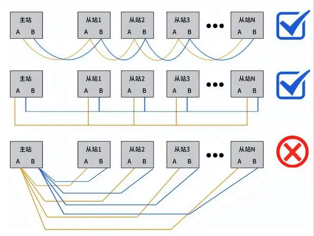
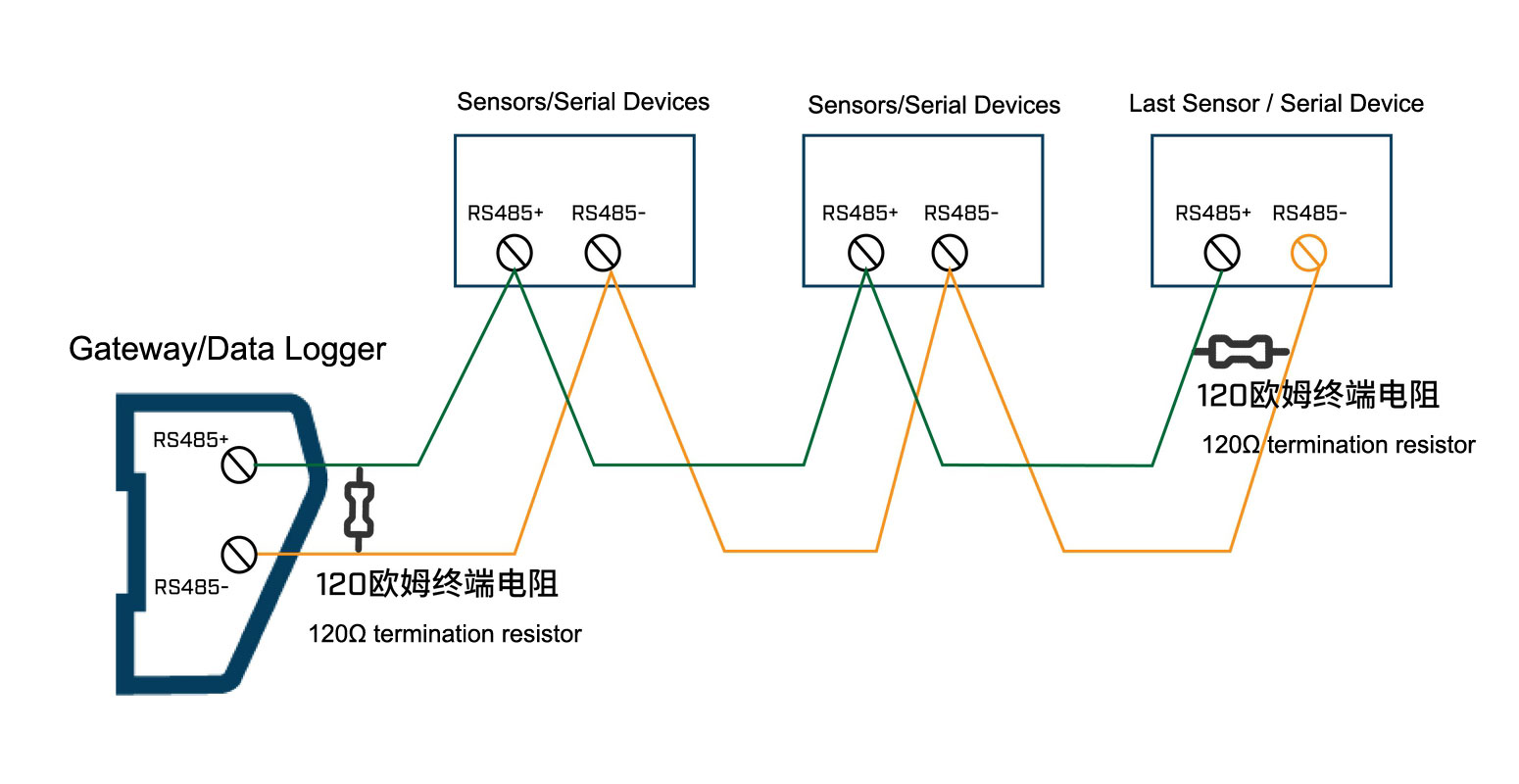
2. Build the bus network:
2.1 Select RS485 bus topology: RS485 supports multi-point communication and can be used in master-slave or multi-master mode. In the master-slave method, the industrial router acts as the master node, while the sensors are slave nodes.
2.2 Connect all RS485 sensors in series through twisted pair cables to form an RS485 bus network.
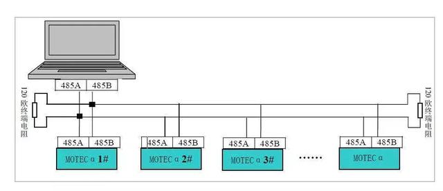
2.3 Terminating resistors (typically 120Ω) may need to be installed at both ends of the bus to eliminate signal reflection and interference. Please note, however, that terminating resistors are not required in all cases, depending on the network configuration and equipment manual.
3. Cable routing planning:
Use suitable shielded twisted pair cables (e.g. CAT5e or CAT6) and design a reasonable cable wiring plan according to the location and layout of the sensors.
Wiring Example:
Power Positive > Sensor Power Positive (+)
Power negative > Sensor power negative (-)
Wire A > Sensor signal wire (transmitter)
Wire B > Sensor signal wire (receive side)
GND > sensor ground
4.Connecting the industrial router:
- Connect each RS485 sensor to the RS485 interface of the industrial router or RS485 converter via RS485 cable (the RS485 signal of the sensor (usually "A" and "B" lines) connected to the router's RS485 interface corresponding A and B lines). (The RS485 signals (usually "A" and "B" lines) are connected to the corresponding A and B lines of the router((Gateway/Data Collector/Data Logger) ) RS485 interface).
- Ensure that the A (Data A) and B (Data B) wires of each sensor are properly connected to the RS485 bus.
- Set the sensor operating mode to RS485 mode according to the sensor manual.
- Configure the sensor's communication parameters (such as baud rate, data bits, stop bits, and parity bits) to match the settings of the RS485 interface of the industrial router.
Note: The addresses of multiple sensors/serial devices need to be distinguished and the serial baud rates need to be consistent.
III. Configuration and Testing
1. Connect the power supply and start the industrial router(Gateway/Data Collector/Data Logger) .
2. Configure the industrial router:
2.1 Log in to the management interface of the industrial router:
Configure the RS485 interface parameters according to the device manual or the guide provided by the supplier.
If necessary, configure network parameters (such as IP address, subnet mask, gateway, etc.) so that the industrial router can connect to the network.
3. Configure the industrial router:
- Set the correct baud rate, data bits, stop bits, and parity bits, which must be consistent with the RS485 sensor communication settings. Usually the commonly used baud rate is 9600, 19200, 38400, etc..
- Configure the RS485 interface parameters to ensure consistency with the sensor's communication parameters.
- Configure port mapping (if required) so that the RS485 port on the internal network can be accessed by the external network.
Modbus Rules Setting
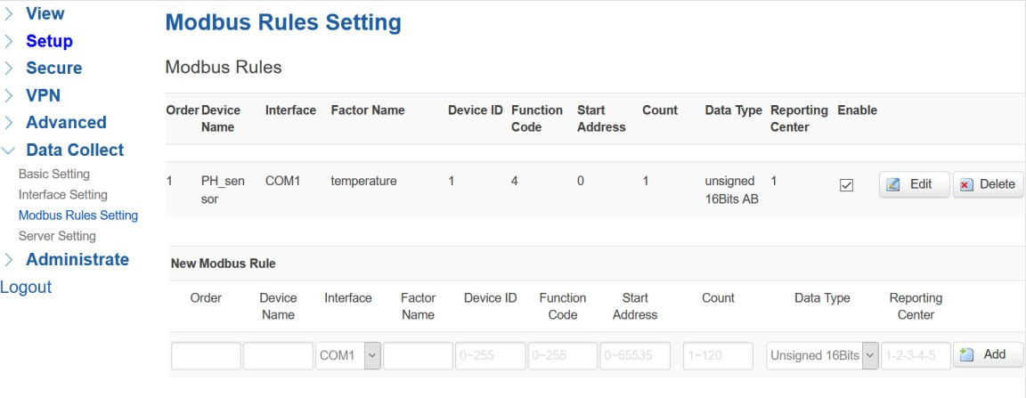
Modbus Rules Setting is for Industrial router as a Modbus master to acquire data from slave devices base on Modbus protocol. You can configure unlimited Modbus rules on it. Industrial router provide the options of definable factor name, device ID, function code, register address and count register number, please following the slave device datasheet to get those information.
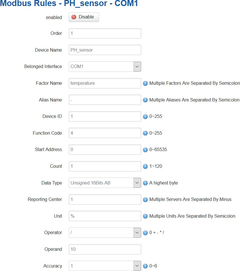
Click “Edit” button for more details setting,
Server Setting
Server setting menu allows user set the data center address with multiple protocols, the standard Industrial router support TCP, UDP, HTTP, MQTT, and Modbus TCP. For the data format,
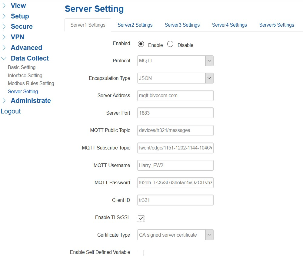
Industrial router support different Encapsulation type, include “Transparent”, “Json”, and “HJ212” (special for some Environment SCADA).
4. Testing and commissioning:
- Perform post-connection testing and debugging to ensure that the industrial router can correctly read the data sent by each RS485 sensor.
-Use a data monitoring tool or software to verify the accuracy and real-time nature of data collection.
- Adjust cable connections, communication parameters, or software configurations as needed to ensure stable data collection and communication.
IV. Data Processing and Storage
Install and configure data acquisition software as needed to receive data from the industrial router and process it.
- Write or configure data acquisition software to read data from each RS485 sensor according to the protocols supported by the industrial router (e.g. Modbus RTU, ASCII, etc.).
- Configure the software to support the management of multiple sensor addresses and data acquisition.
-Ensure that the software can parse RS485 protocol packets and extract useful sensor data.
Data storage:
Store collected data to a database or cloud platform for subsequent analysis and use.
Regular backup and recovery policies can be set to ensure data security and integrity.
V. Maintenance and Optimisation
5.1. Regular check and maintenance:
Regularly check the connection status and device performance of the RS485 bus network to ensure stable system operation.
Clean and tighten the cable connection points to avoid loosening and corrosion.
5.2 Optimise network configuration:
Adjust the configuration parameters of the industrial router, such as baud rate, buffer size, etc., according to the actual demand to optimize the data transmission performance.
Consider using more advanced data encryption and authentication technologies to protect the security of data transmission.
5.3 Ensure that all connections comply with industrial standards and use cables and equipment that meet specifications.
5.4 Consider environmental factors, such as temperature, humidity, dust protection, etc., to ensure proper operation of the equipment.
5.5 Check and maintain the equipment regularly to ensure stable and reliable communication.
Precautions:
- Cable length and quality: RS485 communication distance is long, but still need to consider the impact of cable length on the quality of communication, try to use shielded twisted-pair cable and ensure that the connection is of good quality.
- Communication parameter setting: Make sure that the communication parameters (baud rate, data bit, stop bit, parity bit) of all devices are the same, otherwise, they cannot communicate normally.
- Ground connection: Make sure the ground (GND) of each device is well connected to reduce noise interference in communication.
With the above steps and methods, you should be able to successfully connect multiple RS485 sensors to the RS485 interface of your industrial router and achieve stable and reliable data collection function. This is of great significance for industrial automation, remote monitoring and other fields.
Please note: For specific operations, please refer to the manuals of the relevant industrial routers(Gateway/Data Collector/Data Logger) , sensors and network devices or contact technical support for more detailed instructions. Different brands and models of equipment may have specific setup procedures and requirements.
Related recommendations
Sensors & Weather Stations Catalog
 Agriculture Sensors and Weather Stations Catalog-NiuBoL.pdf
Weather Stations Catalog-NiuBoL.pdf
Agriculture Sensors Catalog-NiuBoL.pdf
Water Quality Sensor Catalog-NiuBoL.pdf
Related products
 Combined air temperature and relative humidity sensor
 Soil Moisture Temperature sensor for irrigation|NBL-S-THR
 Soil pH sensor RS485 soil Testing instrument soil ph meter for agriculture |NBL-S-PH
 Wind Speed sensor Output Modbus/RS485/Analog/0-5V/4-20mA
 Tipping bucket rain gauge for weather monitoring auto rainfall sensor RS485/Outdoor/stainless steel
 Pyranometer Solar Radiation Sensor 4-20mA/RS485

Screenshot, WhatsApp to identify the QR code
WhatsApp number:+8615367865107
(Click on WhatsApp to copy and add friends)

